One day I found a board with vacuum indicators at a local flea market. Specifically, the NL8842/5991 from National Electronics.
I simply couldn’t miss the opportunity to buy it for 50 shekels. Moreover, the lamps looked intact and working. After a short search, I managed to find the datasheet. However, I couldn’t find the footprint of its socket, so I decided to draw it myself based on the diagram. I’m posting it here for Altium. I also uploaded it to EasyEDA. I decided to build the clock control on an ESP8266 using the Arduino platform. I implemented the lamp control logic according to this circuit:
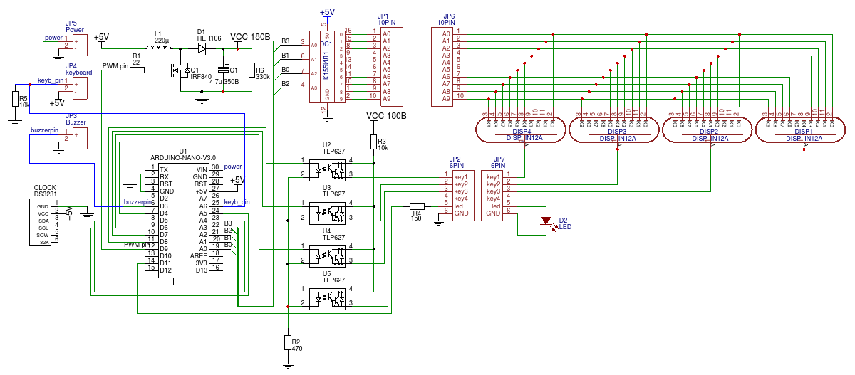
Circuit from here:
I replaced the decoder with an SN74141, which I found on the purchased flea market board. The lamps are powered by 170 volts, so I needed to build a small step-up circuit. But by chance, I managed to find a ready-made one among my collection of AliExpress boards.
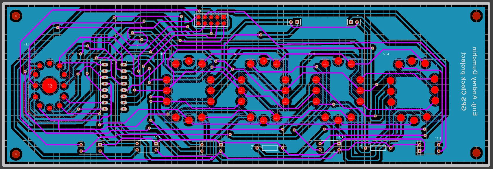
I ordered the PCB from JLCPCB.COM. Once again, their quality did not disappoint me.
Everything works. The clock gets the exact time via the NTP protocol. I noticed that adjusting the brightness of the lamps is not that simple, so I decided not to overcomplicate things. I will add buttons for manual time request/setting and install a real-time clock (RTC) module with a battery in case of power outages.
By the way, in addition to the 4 main lamps for hours and minutes, I installed another one for symbols – an IN-15A, which was sent to me by a friend from Mykolaiv.
Now the only thing left is to make the enclosure. The dilemma – make it from several pieces of wood or order it as a single piece from a CNC?
UPD 22.09.2020
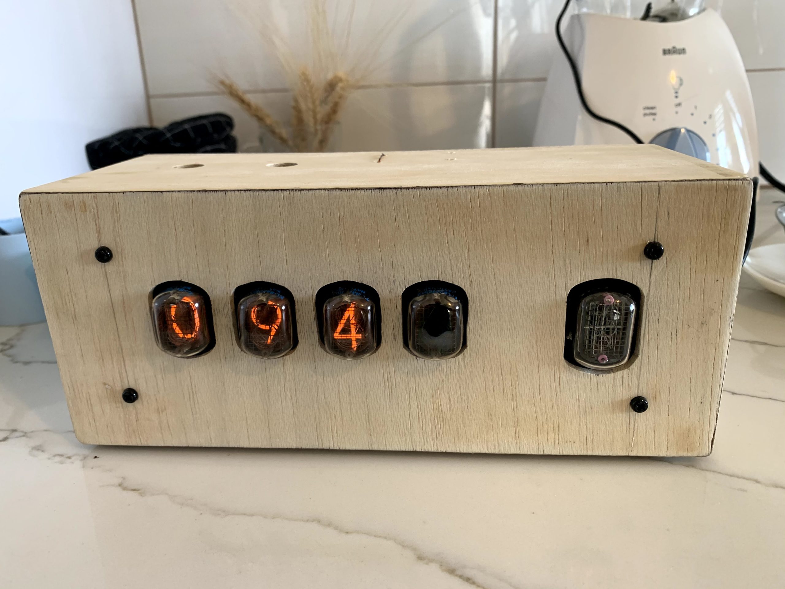
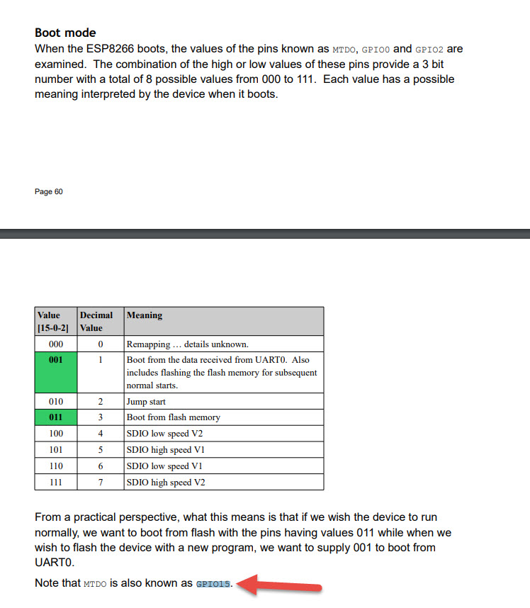
My dad made the box for me out of thin plywood. But when I assembled the clock in it, it suddenly stopped working. I checked absolutely everything… But what did it turn out to be in the end? In the ESP8266, which the clock is built on, three GPIO pins – GPIO0, GPIO2, and GPIO15 – must be in a certain state for the boot to occur from flash memory. Here is an excerpt about this from a book:
I changed one of the pins in the program that was connected to one of the optocouplers. Now everything works perfectly.
I should also add buttons for manual time correction. I decided to abandon the RTC module. The clock connects to a server via NTP and gets the time itself. Not all digits are visible in the photo due to the multiplexed driving of the lamps.